AI copilots for manufacturing design and product reliability.
Your engineers model in CAD; Design Copilot turns those models into dimensioned 2D drawings. Your quality teams run FMEAs; AI FMEA Suite does the heavy lifting. Use either on its own, or both together.
- Manufacturing drawings generated
- FMEA entries processed







A finished 3D model isn't a finished part.
Before it can be made, someone turns it into a drawing: views, dimensions, GD&T and notes, by hand, sheet by sheet.
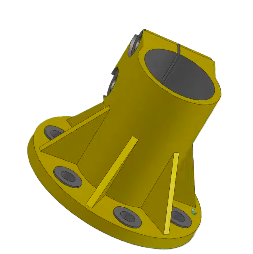
3D model
Done in CAD
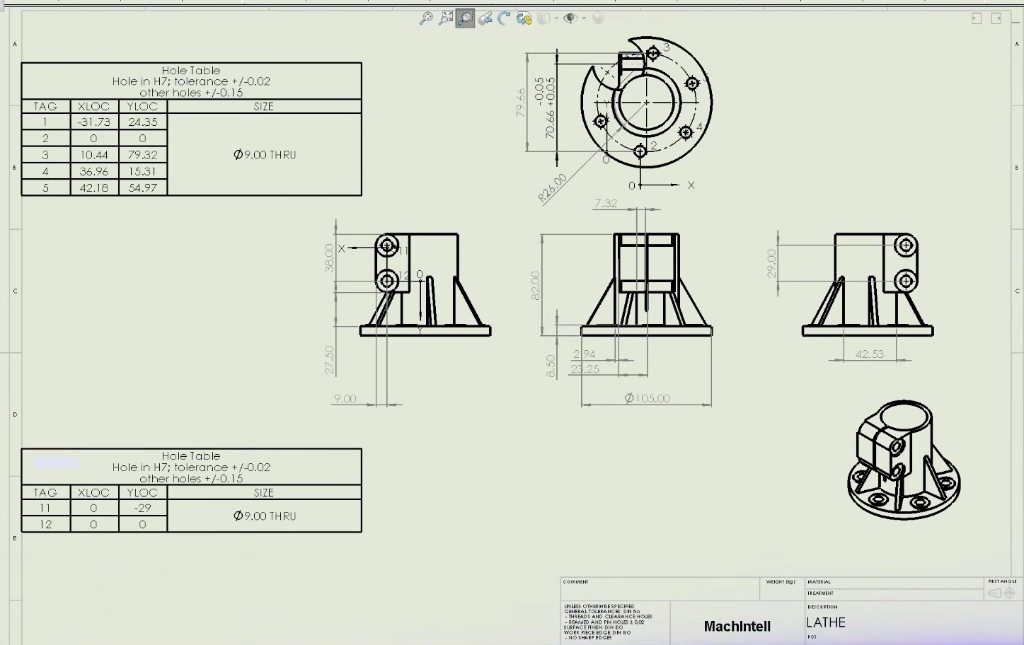
2D drawing
Now multiply it by every part in the program.
With Design Copilot, consistent drawings are ready in minutes, and your engineers review instead of drafting.
 CopilotDrafting10:14 AM
Create a fully dimensioned 2D drawing of this flanged bracket: top, side and section views, hole table and GD&T, on an A3 sheet with our title block.
- 10:14:02 AMReading SolidWorks part…
- 10:14:03 AMPlanning view layout…
- 10:14:05 AMPlacing dimensions and GD&T…
Describe the drawing you need in SolidWorks…
Design Copilot turns 3D models into release-ready 2D drawings
Design Copilot plans the views, dimensions and GD&T for each part, then converts your 3D CAD into fully dimensioned manufacturing drawings, ready for review and release. Engineers approve every suggestion, so drafting time drops without cutting corners.
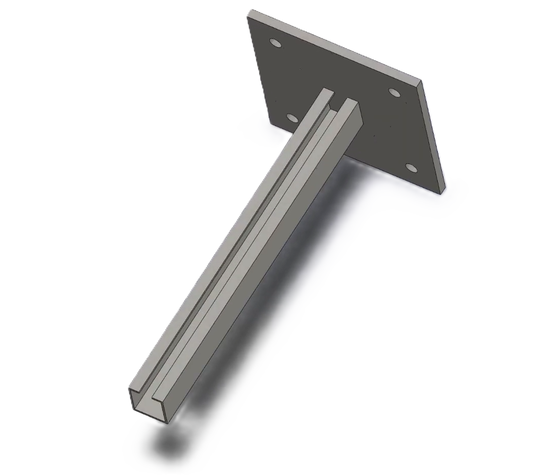 CopilotModeling03:51 PM
Square wall base plate with four corner anchor holes and a single 41×41 strut channel arm, welded perpendicular to the plate. Overall 200 × 200 × 410 mm, hot-dip galvanized S275 steel.
- 03:51:25 PMReading SolidWorks context…
- 03:51:25 PMThinking…
- 03:51:25 PMGenerating the build plan…
Describe what you want to do in SolidWorks…
Overall: 200*200*410 mm, material Plain Carbon Steel. Auto-approve is on for this session. Building 4 step(s)...
Generate manufacturable 3D geometry from a prompt or a sketch
Describe a part or upload a rough sketch, and Design Copilot generates manufacturable 3D geometry with design intent and tolerances preserved. It works alongside the CAD tools your team already uses, so nothing about your release process has to change.
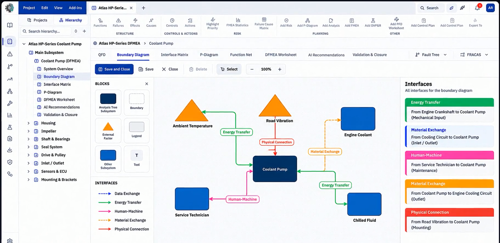
Brake caliper mount fatigue crack
Run AI FMEA on your designs, not in spreadsheets
AI FMEA Suite builds block diagrams, parameter diagrams and interface matrices directly from your design, then links them to failure modes, risks, actions and controls, so mitigations are in place before anything reaches production.
Across 15+ drawings, repetitive view, dimension and annotation work was noticeably reduced.
Reviewing 20+ failure modes became more direct, with less back-and-forth to the related design details
Connect every step into one reliability thread
ReliabilityOS, Draw AI and FMEA Execution work as one connected digital thread for engineering, manufacturing and quality teams. Each runs on its own, but together they carry design intent from the first concept through to field confidence.
Connecting MachIntell to the CAD tools you already use is fast and easy.
Design Copilot works with major CAD software, including SolidWorks, CATIA, Creo, Siemens NX, Onshape, Solid Edge, Inventor and Fusion 360, so it fits into your existing systems without extensive retraining or overhaul.
Learn more about integrationsMachIntell